Post written by Jared Banks in 2016
This is the ninth post in my endless series on Pens and Pen Sets in Archicad. In this article I’ll cover how Graphic Overrides have affected Pens and Pen Sets and then discuss a number of examples. I’m assuming you’ve read many or all of the previous Pen Set articles. If something I discuss below references a previous post, I’ve tried to note that. If you want to take the entire Pen Sets Journey starting with my views dating back to Archicad 11, here are links to all the previous posts:
- Pen Sets, Part One
- Pen Sets, Part Two
- Pen Sets, Part Three
- Pen Sets, Part Four
- Pen Sets, Part Six
- Pen Sets, Part Seven
- Pen Sets, Part Eight
Archciad 9 to 10 and Archicad 19 to 20
Graphic Overrides, which were introduced in Archicad 20, upend our relationship with Pens. It’s as monumental a shift as the transition from Archicad 9 to 10, when GRAPHISOFT introduced multiple Pen Sets. With the introduction of multiple Pen Sets, we finally had the ability for one pen to be many things; a pen switched from being an Attribute with a static set of parameters to a parameter of an Attribute that could vary by View (Pen Sets being the view-based Attribute). A pen could be thick in plan but thin in section. One pen could be color on the screen but black for printing, while another pen could be color on both the screen and paper. With Pen Sets we could change the color or thickness of a Pen, but we couldn’t change what Pen is assigned to an element. We could only change how that individual pen globally appeared in a given View. With Graphic Overrides, we can now replace one Pen with another, selectively at the element level. We can thus change the Pens of one element while keeping the Pens of another element unchanged.
Pen Sets change the display of Pens for an entire View.
Graphic Overrides change the display of Pens for an entire Element.
Graphic Overrides can of course change the display of not just Pens, but also Fills and Lines. In this article we’ll focus primarily on Pens, but the theories discussed apply to all the other ways Graphic Overrides can affect elements.
Just One Pen Set
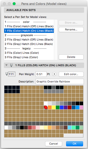
In the image above, you’ll count nine Pen Sets. Three are dummy Pen Sets I use as list separators (Layer Theory Part 5). Two are old-school gray versions of my colored Fill Pen Sets. I never use these, but since I share my template, I don’t want to force everyone into my ways. I work in color, save PDFs in color, and then print those directly with color or black and white printers, depending on sheet size and cost (which is what you should do too). The final two Pen Sets are old-old-school where color = line weight. These are model checking Pen Sets. Every once and a while, I’ll temporarily switch to these as a quick visual check that my file is following my own rules. They are on screen only Pen Sets. I treat them like I do model checking Graphic Overrides: something to cycle through when I’m validating my work (more on that later).
In the ten years that Archicad has had multiple Pen Sets, I’ve expanded and contracted the number of Pen Sets I’ve used. I used to have Pen Sets for working and Pen Sets for printing. I had Pen Sets for schematic drawings and Pen Sets for half tone drawings. For a while I had a Pen Set for detail drawings. Now I effectively have two: one showing hatches and one hiding hatches (Pen Sets, Part Four). If I didn’t want to turn hatches on and off, I could get away with one Pen Set. It feels bizarre to come full circle. And yet one Pen Set in Archicad 20 (with the complimentary power of Graphic Overrides) is infinitely more powerful than one Pen Set in Archicad 9.
Graphic Overrides replace Pen Sets, not Pens
It’s more complicated than Graphic Overrides replace Pen Sets not Pens, but if you look at Graphic Overrides from that perspective, you’ll be better prepared to master this new feature. With Graphic Overrides, I was able to get rid of four Pen Sets: Half Tone, Schematic, Uniform Line Weights with colored fills, and Uniform Line Weights with gray fills (Pen Sets, Part Eight). I also eliminated four pens from the remaining Pen Sets. But then I added six more pens (and moved four). Graphic Overrides removed Pen Sets but actually added Pens. Here’s a breakdown of what my Pens look like now:
- Pens 1 through 4. Generic thickness pens that are unrelated to modeling pens
- Pens 11 through 15. Contour Lines, Thin Lines, Fill Lines, Windows/Doors, Plumbing
- Pens 21 through 24. Annotation Pens
- Pens 31 through 35. Always gray lines
- Pens 91 through 100. The classic Grayscale ramp
- Pens 111 through 120. My new Graphic Override Rainbow
- Pens 181 through 220. My Fill pens (Pen Sets, Part Eight)
As mentioned earlier, in Archicad 20 Graphic Overrides affect entire elements, not portions of elements. We can change all the lines from Pen 1 to Pen 2 in a Composite Wall, but we can’t change only the cut lines or only the foreground pen of one Skin. It’s all or nothing. That means Pens still give us more control over sub-elements. Graphic Overrides can not yet replace my fill pens (Pen Sets, Part Seven).
From One to Four to Ten
My Pen Sets are more and more about rainbows. While I have a few pens that are linked to specific things in Archicad (more on those pens in a future post), the majority of my pens are becoming disconnected from anything specific. The pens are about graphics. Graphics that I can control how I see fit. Graphics that are becoming more automatic and controlled more and more at the Project level (Element, View, and Project Data).
I don’t know what I need to override, but I know I need these pens to be independent of everything else so that typical graphics don’t interfere with special graphics. It’s an extension of my old Pen #20 (Pen Sets, Part One) that then expanded to four pens (Pen Sets, Part Seven): #20, #40, #60, and #80 (plus pen #100, which is always black). For a long time I had the concept of pens that never changed color. The idea was that even if I printed to black and white (ei, saved a PDF), I could still have some color. It was also great for on screen notes and checking. But it was all manual. With Archicad 20 and Graphic Overrides, I decided to create a rainbow of pens that would be used for Graphic Override purposes. They might be used for highlighting elements for model checking or creating a printed graphic that pops. I don’t really know their final purpose. But I do know that I want access to special pens and colors that allow me to do anything I need.
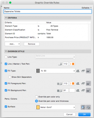
It’s important to remember that your Pen Set needs to have the pen color/thickness you want to override to. You can’t create a Graphic Override Rule that turns all expensive toilets to gold, if you don’t have a gold colored pen in your Pen Set—or a gold Surface or a stylized gold Fill, if you’re switching the Surface and Fill as well. Furthermore, you also need a good way to make sure your file knows what Objects are expensive toilets and which aren’t. If I were seriously creating the GO Rule in the image below, I’d find a better solution than relying on ID to identify toilets.
Hello Old Friend, Part 1
Graphic Overrides offer a massive list of Criteria to choose from when setting up what will be affected by a Graphic Override Rule. I have yet to dig into all of them and even looking at the list can be a bit overwhelming—it’s a mammoth catalog of answers in search of problems to solve. One simple answer in search of problems to solve is Color by Layer. Color by Layer is a powerful solution that hearkens back to days of old when many of us used another software—a software that was all about color by layer.
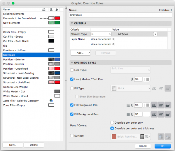
Grayscale (most things, some of the time): Prior to Archicad 20, we needed a Pen Set to create Grayscale plans. You could (and still can) change a placed View on a Layout to grayscale, but that’s a sledge hammer solution and we should almost never use it. The optimal solution is to use Graphic Overrides. Below is GO Rule for Grayscale. You’ll notice it turns all lines and fills to gray, and also overrides both the pen color and thickness. You could just as well override only the pen color, if you wanted to maintain the original thickness. But my preference is to make grayscale elements uniform. In the example below, I’m turning everything but Layers that does not contain 5 | or does not contain 6 | to a gray pen. Now that language is a little odd, but it’s necessary. Archicad provides us with the option to select Layers that starts with or ends with a particular value. But we don’t have does not start with. Fortunately for my layering system does not contain and does not start with are equivalent functions. It’s also worth noting that my layer strategy is such that layers that start with 5 | are structural layers and layers that start with 6 | are electrical or mechanical layers.
Using Graphic Overrides to produce grayscale drawings allows me to remove my grayscale pen set and remove pens that were dedicated to structural and electrical elements. I used to have annotation pens for architectural drawings and annotation pens for grayscale drawings (Pen Sets, Part 3). This allowed me to have some annotations gray out and others stay black. Controlling grayscale by Layer removes this complexity, as my architectural annotation are on a Layer that gets converted to gray while my structural and electrical annotation does not. This means I now use the same pens for all my annotation and the only difference is Layer. The complexity of my drawing management decreases as the remaining complexity shifts from element based data to view based data. This is a good move as the difference only matters for the View, not the element.
Hello Old Friend, Part 2
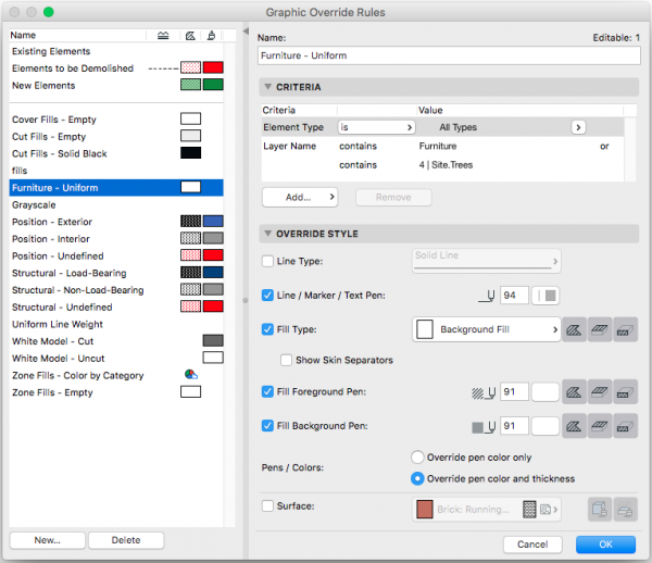
Grayscale (some things, most of the time): I don’t use the out of the box Pens (obviously). One downside to that is that all the pens in all the Objects are wrong for me. My original logic was that this was okay because it forced the user to look at the Objects being used. It encouraged ownership. That’s great, but it’s also a pain because there are some elements whose settings I don’t care about. I just want them to look good in 2D and 3D. Their data is relevant. This is particularly the case with entourage: furniture, landscaping, people, cars, etc. Graphic Overrides once again give us an amazing solution. I have a Graphic Override set up to turn all elements on my Furniture or Trees layers to have a white Background Fill and uniformly thin gray lines. I love this because it allows me to ignore the majority of 2D settings in all the Objects I’m placing in my model for primarily 3D purposes. I can now place any bed, couch, table, plant, coffee pot, tv, or whatever I want in my model for rendering and just worry about the Surfaces. The 2D graphics will be automatic and uniformly perfect.
Again, note that because of the language available for Layer Name selection I chose what may appear to be an odd choice: Layer Name Contains. I did this because I wanted to both select a specific layer (4 | Site.Trees) and a general grouping of Layers (I have two furniture Layers).
Hello Old Friend, Part 3
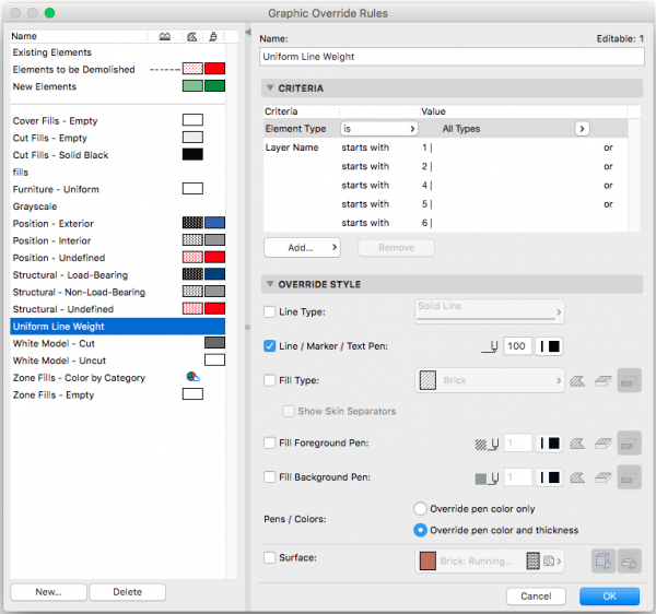
In 2014, I wrote an article on uniform line weights for sections: Building Materials – One Example to Rule them All. Switching to uniform line weights for sections was liberating. It removed an entire segment of drawing management. I can’t believe how much time I wasted on unnecessary line weights in sections. Uniform line weights for sections is now one of my non-negotiable graphic beliefs. It’s beautiful, efficient, and easy. Prior to Archicad 20, I handled uniform line weights with a special Pen Set. That was fine, but not ideal. Graphic Overrides allow a stronger solution. I handle uniform line weights with a Graphic Override Rule that overrides all elements on particular Layers.
By the way, if your Layers aren’t organized in a manner that makes all this Color by Layer magic work, read my series on Layer Theory, particularly Archicad Layer Theory Part 5: Attribute Names and the Tyranny of Alphabetical Order. That post will cover the theory behind how you need to organize your layers.
More than Just Color By Layer
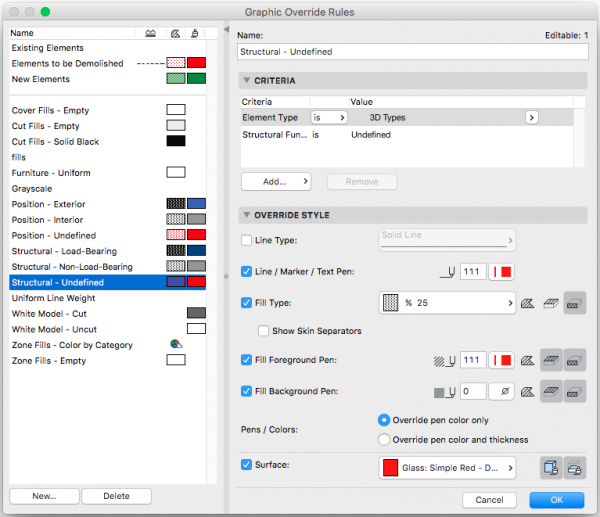
While my first three examples focus on 2D output, Graphic Overrides and their relationship to Pen Sets are equally important to model validation (in both 2D and 3D). As we move towards more direct model sharing (via IFC or using the BIM Server to coordinate across multiple offices and disciplines in one file), it becomes critical for us to know if our data is correct. We can export the IFC model to Solibri Model Checker or other programs to run scripts and check against rules. But we can also do some of that work within Archicad. While more manual in Archicad (let’s call it semi-automatic), the advantage is that you can readily make immediate changes to your model. Also it encourages you to start using more of the functionality of Archicad. We’ve had Position (exterior/interior/undefined) and Structural Function (load-bearing/non-load-bearing/undefined) for many years now. But I’d wager most of us haven’t been using them much. Setting up Schedules that rely on this data is great, but if it’s not easy to verify, it can be dangerous. That’s why I continued to use Layers to manager my window and door schedules through Archicad 19. I’ve switched to Position in Archicad 20 because I can now do a quick visual check of the model to make sure all my windows have the correct position.
This may seem like a minor shift, but it’s the foundation for larger changes. Position and Structural Function are now always correct in my models. That means I can build processes based on these attributes (like schedules) and am also one step closer to more complex data exchange. I still primarily work by myself or with one other architect and get hand drafted red lines from engineers, but my models are ready for so much more. When I land a larger project that requires OpenBIM data exchange, or a future feature of Archicad offers some other powerful technique, my models will be ready. Being able to change the color of elements in 2D and 3D (Pen Sets, Part Six) to quickly check the correctness of a singular piece of data is critical to increased intelligence and future proofing. Furthermore, it’s a wonderful feeling to know how much smarter my models are in Archicad 20 than they were in ARCHICAD 19.
Next Steps: Order of Operations
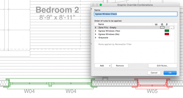
In this article I’ve been discussing individual Graphic Override Rules, not Graphic Override Combinations. Graphic Override Combinations deserve many posts of their own, but let’s wrap up this post with one key point about Graphic Override Combinations: when combining rules, order matters. GO Rules higher on the list of Rules take precedent over GO Rules lower on the list. If you have a rule that turns all layers gray and another rule that turns all egress windows green, make sure the the egress window rule is applied before the all layers to gray rule. In other words make sure the specific comes before the general. In the image below, if Grayscale came first, I wouldn’t know which windows were Egress Windows and which weren’t.
Thank you for reading almost 3,000 words about Design
All of this discussion about Graphic Overrides is really just about design. The egress window checker is the easiest example of this. We all deal with egress windows. It’s pretty basic stuff. So basic that most of us just naturally size windows correctly and move on, not even worrying about it. Having a quick 2D and 3D visual though reminds us that egress windows are about health, safety, and welfare AND design. If we check our floor plan and realize we have way more egress windows than we need, perhaps we decide to play with some of them, because we can. Or we might look at our plans and realize that, while it meets code, it’s foolish not to tweak a few windows to make them also safe points of exit in case of emergency.
Are you following Graphisoft North America on Twitter? Click Here to keep track of all the latest Archicad News in North America (and beyond).
You might also like:

More Articles:
Archicad
Customer Stories
Education
Industry News
Tips, Resources + Downloads
Webinar Recordings