 United States site instead?
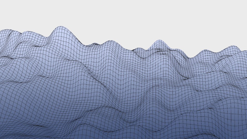
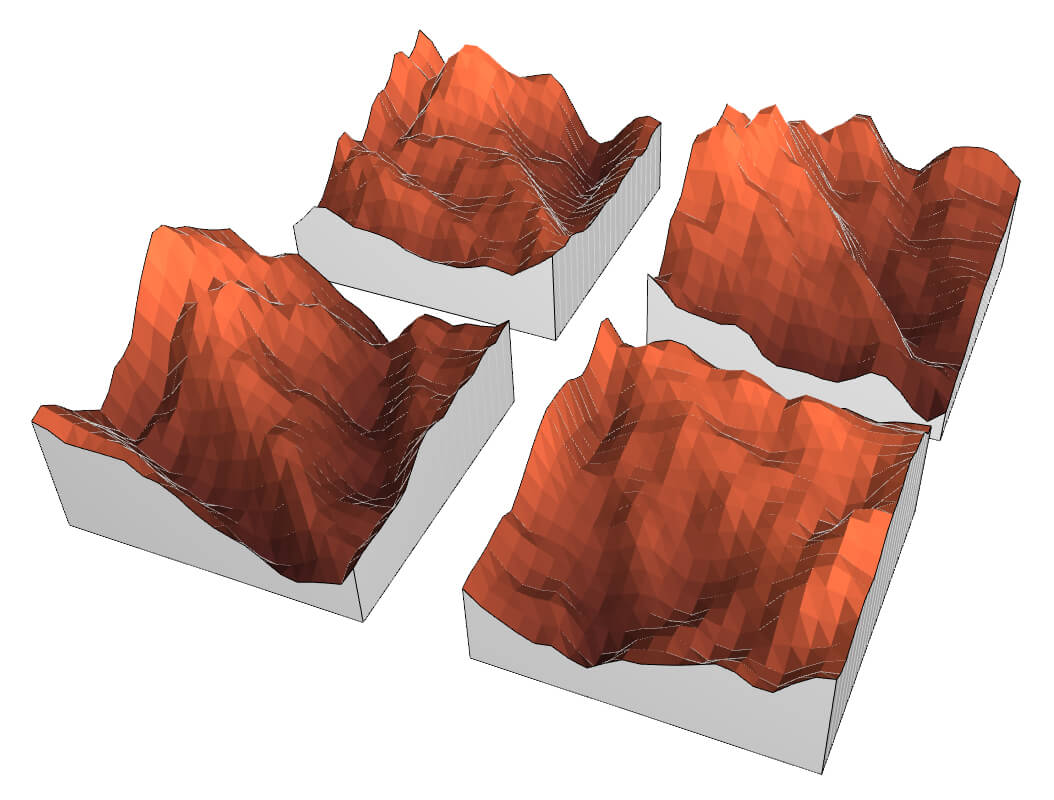
The greater the number of octaves, the more the different noise levels will stack on top of each other to produce a result that is more “detailed” and “interesting”. This effect starts to diminish after about 7 octaves. Each octave is effectively a new loop of calculations, and they increase the processing time almost linearly.
Below is the comparison of how the octave values affects the generated result.
Permutation table
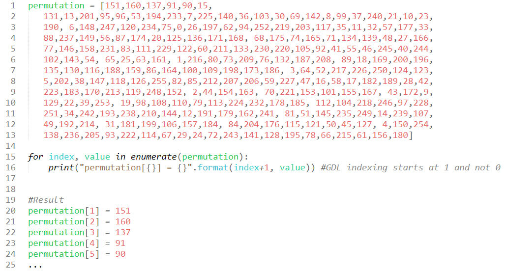
To generate the noise field in a pseudo random way, a lookup table is required. To get the original one as defined by Ken Perlin, we created a simple Python script, then copied and pasted its output into the GDL editor.
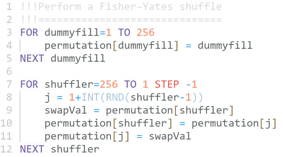
For a random noise field generation from different lookup tables, a simple shuffle algorithm was used. It does not have a very even distribution, but it’s enough and it’s extremely fast.
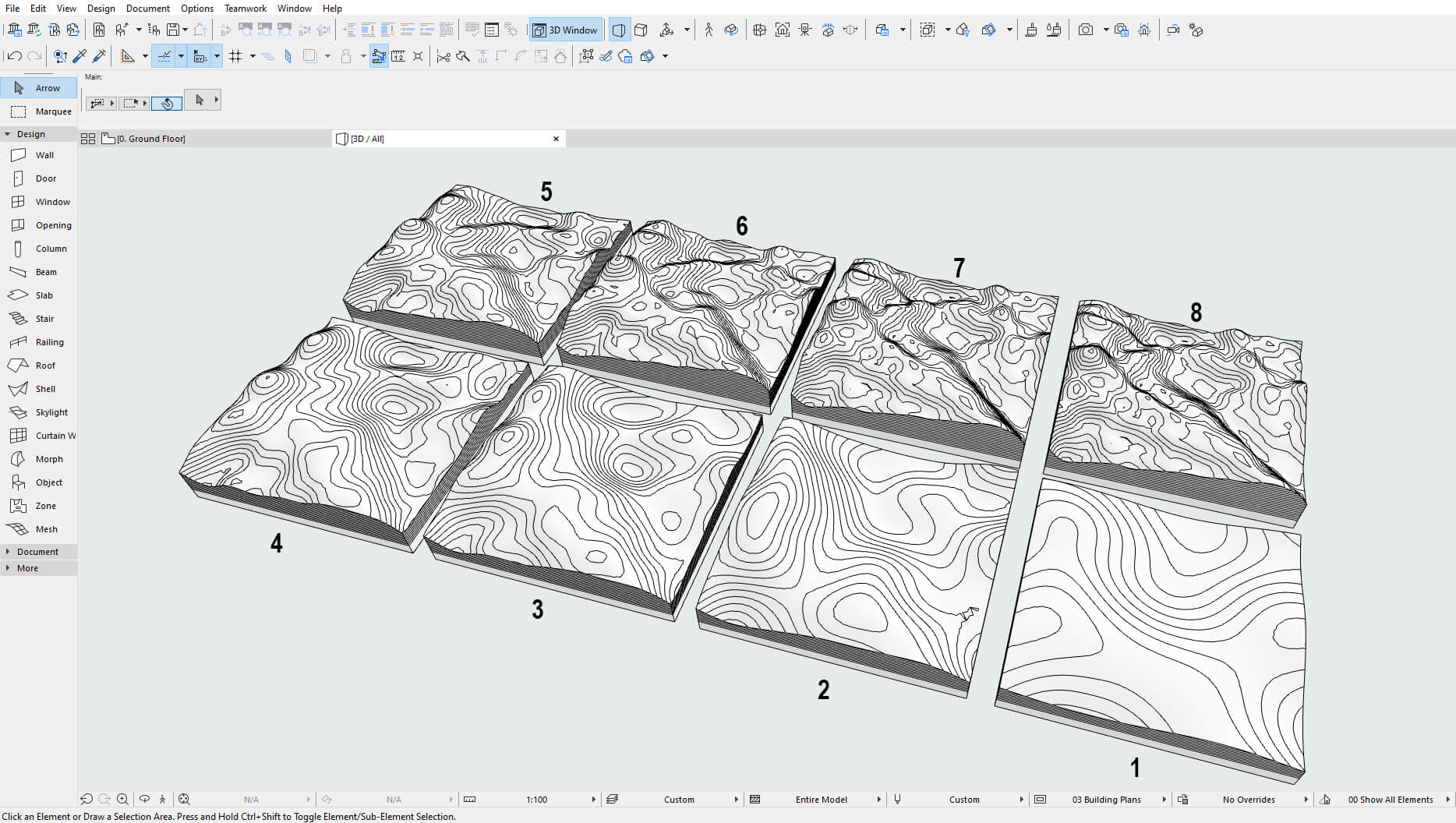
Using the Different terrain each time toggle will generate terrain from a randomly generated lookup table each time the object is placed. If you move or rotate the generated object, it will stay unchanged.
Functions in GDL
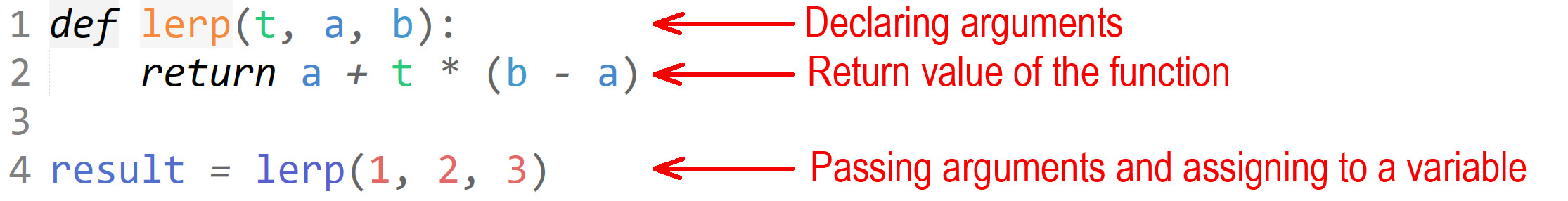
Let’s take a look at how functions are written in a widely used programming language, such as Python.
Very straightforward. However, functions in their usual form are not present in GDL. Instead, GDL uses macro calls that are used to generate geometry.
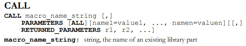
These macro calls use the object name as the “function” name, and they pass parameters to get the result, very intuitively. But this approach has a drawback. You can’t pack all the logic inside a single GDL object – you have to generate it as a library. This makes sense for development tasks overall, but for creation of standalone objects in a user-friendly way, you would prefer to generate everything without building it into an LCF library. You can even use macro calls recursively.
To avoid using macro calls, an alternative is the use of subroutines and parameter buffer. Here is an example of such an approach.
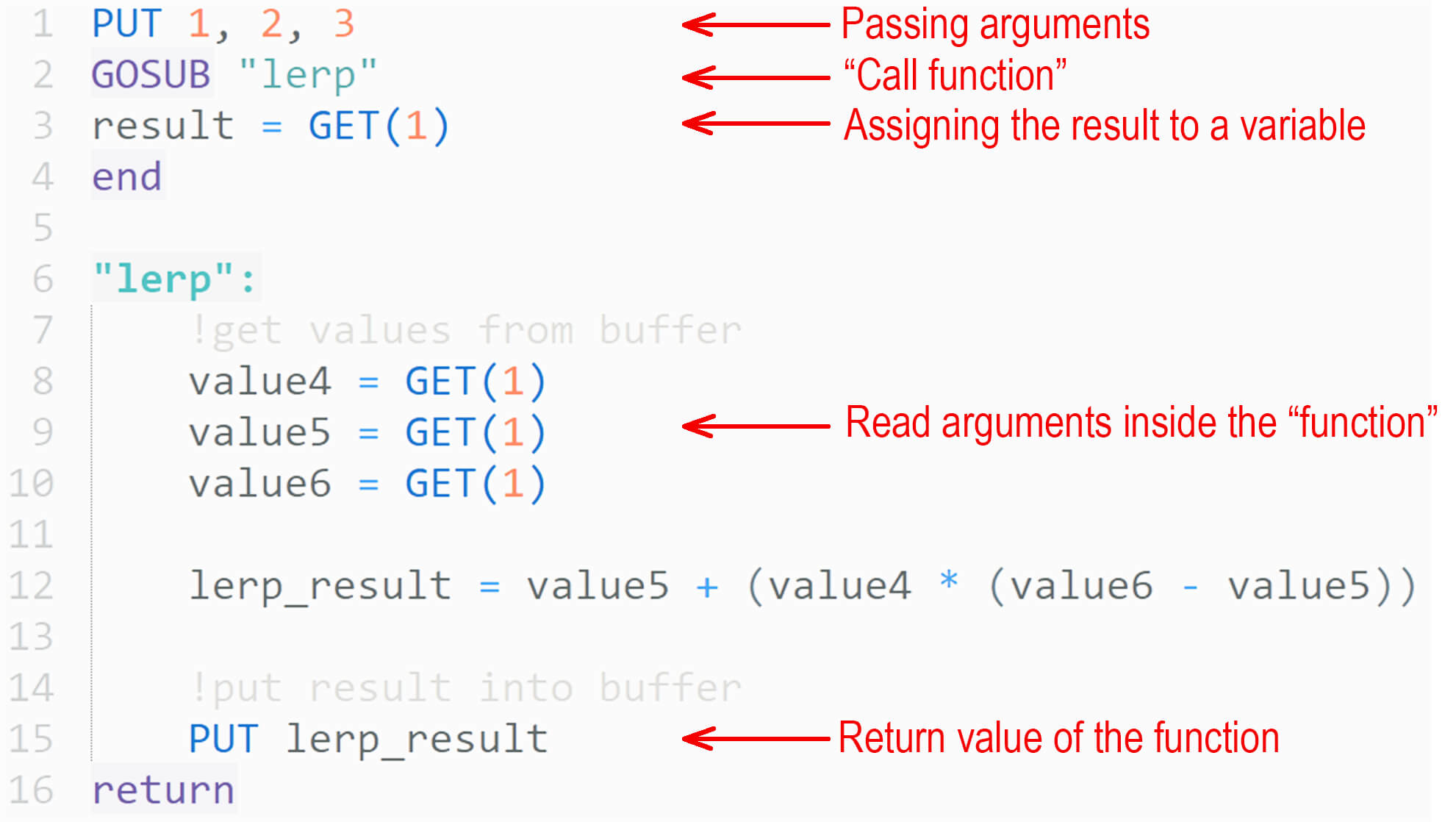
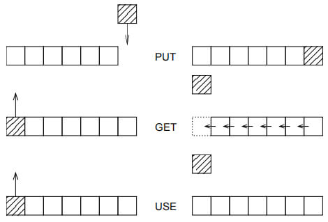
Here is the visual explanation of how the parameter buffer works, from the GDL Reference Guide.
Bitwise operation in GDL
There are only two key operations in GDL, and luckily, they can be used to recreate all the others.
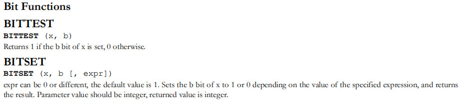
Bitwise AND is needed to perform the noise field generation.
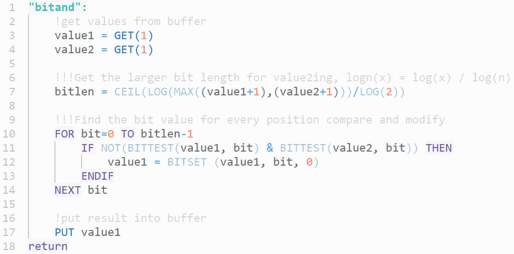
To perform the operation, the bit length of the larger input number has to be determined, to avoid performing unnecessary computations. After the bit length has been determined, all bit values are checked between values, one by one. If at least one of the bit values is 0, then the bit value on that position is changed in the tested number.
Animating objects in Archicad
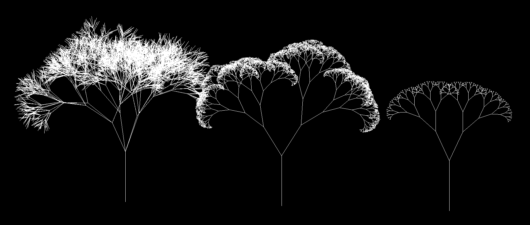
The objects don’t actually move – Archicad can only rebuild the object for each frame, if the checkbox is checked in the Create Fly-Through panel. The object does not communicate to itself between frames, so all the logic has to be embedded from the beginning. The parameter that changes is the GLOB_FRAME_NR. This is the frame number that is currently rendered, so the entire transformation has to be controlled by this single number. With the terrain, it is quite simple: by offsetting the noise field with each frame, it starts to look as if it were moving. Pretty much anything imaginable can be animated. On the left is a snow “particle system” which is completely generated inside Archicad.
Different geometry options
You can approach creating geometry in many ways. For the terrain generation use case, the easiest approach is to use the MESH, which generates geometry in the same way and with same functionality as the Mesh tool in Archicad. Its only inputs are the grid sizes in x, y directions, and the z values of each node.
Generating a colored representation is trickier. First, the grid values are sorted into an array of x, y, z values for each point. Then a loop goes through them, picking and processing pairs of triangles for each node. The color value is calculated relative to each triangle’s average z position. CSLAB_ is used here because it has simple inputs to generate the sides. CSLAB_ also has separate input for top sides and bottom colors, as it’s a fixed z axis extrusion. All the excess is cut with the CUTPLANE command. For a “quad” mesh, we use the same sorted array that was generated for colored mesh, but instead of using CSLAB_, we use PLANE_, with the diagonal edge smoothed by using the respective status code.
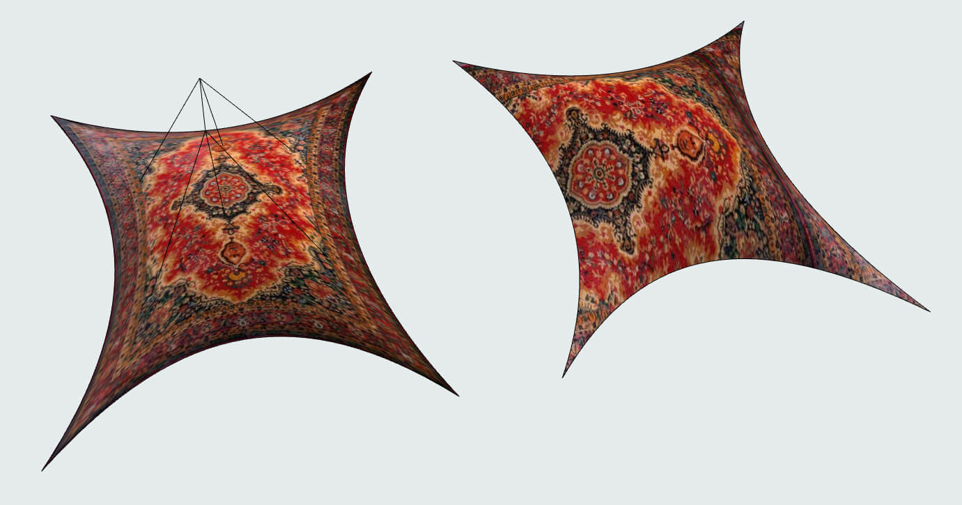
NURBS generation is the most complicated. To generate a NURBS, you have to visualize the indexing structure of all the points in the grid, because you have to specify the edges of the surface and sort them in a particular order corresponding to the point network of the NURBS surface. NURBS has interesting properties – its texture mapping makes it easy to deform the texture any way you like.
Heightmap with GDL
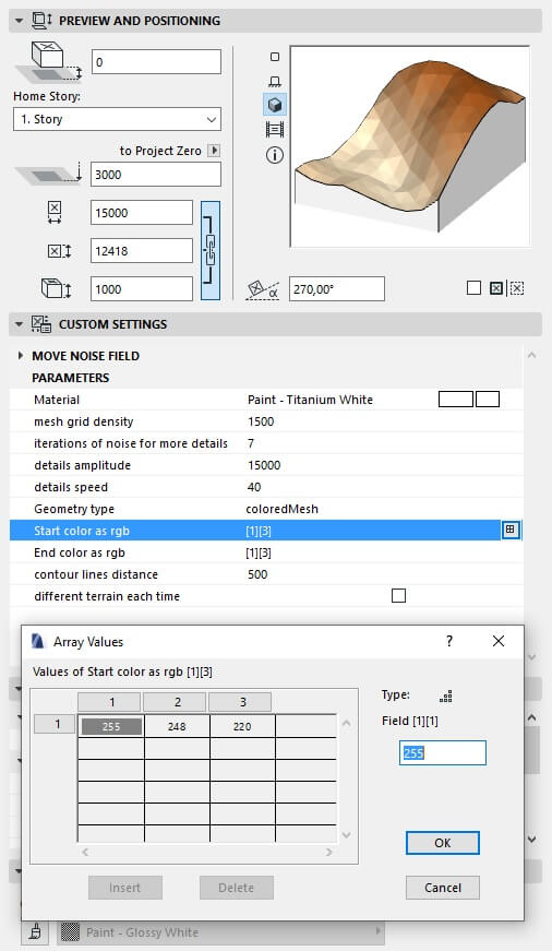
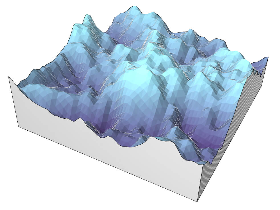
To receive a color gradient on the mesh from one color to another, pick colored Mesh as Geometry type, then fill in start and end color RGB values into the array field which pops up. Start is considered the lowest z coordinates of mesh planes, with end being the highest. Gradient is calculated by remapping the R, G and B domains of color onto the z domain of mesh planes.
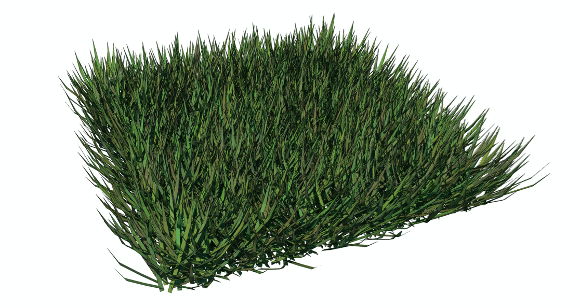
Color generation inside GDL script is done by using the DEFINE MATERIAL command. It has a wide range of input data for controlling all parameters of a material, but for a simple color, a predefined material type matte is enough. The domain of RGB input values is 0.0 to 1.0 (not 0 to 255).
DEFINE MATERIAL grass_rnd 2,
(76+INT(RND(40)))/255,(110+INT(RND(50)))/255,
(INT(RND(30)+60))/255
MATERIAL grass_rnd
About Pavlo Menshykh
Pavlo Menshykh is an architect and BIM Manager at Savytskyy Design (Lviv, Ukraine), which specializes in hospitality industry projects. Pavlo also consults on computational design for Splash Modular and Finch3D.
Pavlo has been using Archicad – Ukraine’s most popular BIM software – since 2012. He is also experienced in Rhinoceros with Grasshopper and Revit. He mentions, “I use a variety of different tools, but Archicad is still my main and favorite one.”
About Graphisoft
Graphisoft® ignited the BIM revolution in 1984 with Archicad®, the industry first BIM software for architects. Graphisoft continues to lead the industry with innovative solutions such as its revolutionary BIMcloud®, the world’s first real-time BIM collaboration environment; and BIMx®, the world’s leading mobile app for lightweight access to BIM for non-professionals. Graphisoft is part of the Nemetschek Group.