This expert material is a follow-up to the “Archicad: revisiting” series of articles launched in December by Vladimir Savitsky with “Creating structures and retrieving shop drawings from the model,” in Russian and is meant to help users unlock the full potential of Archicad®. We have asked architects to share their own experiences in using the software to apply unconventional approaches, less-studied functions and new opportunities that many users may not be aware of at all. This article was adapted from the Graphisoft Russian case study site.
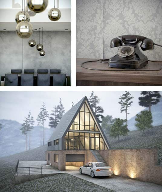
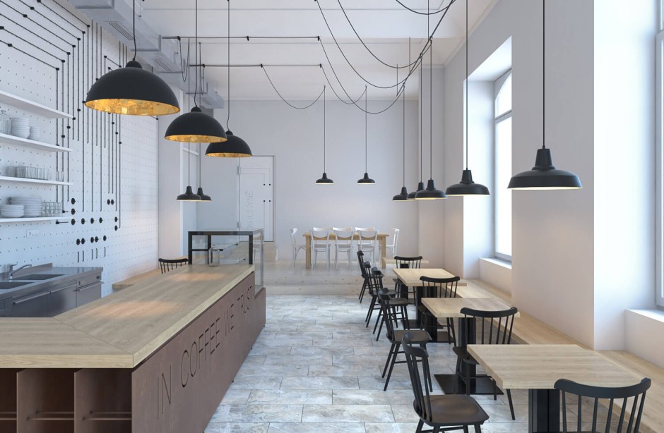
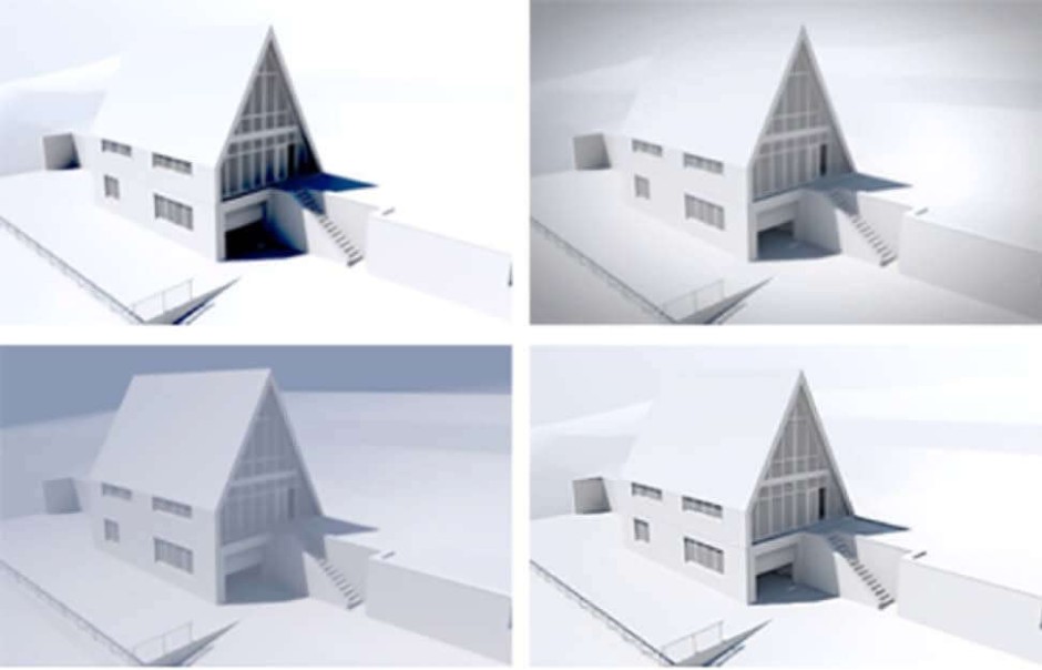
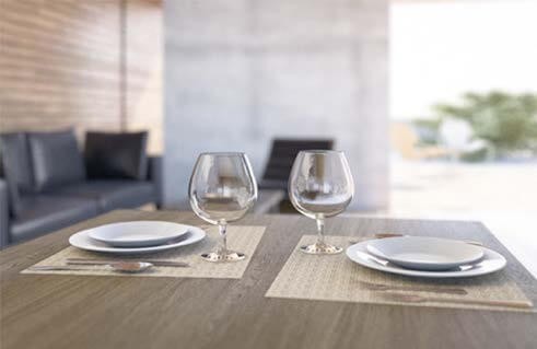
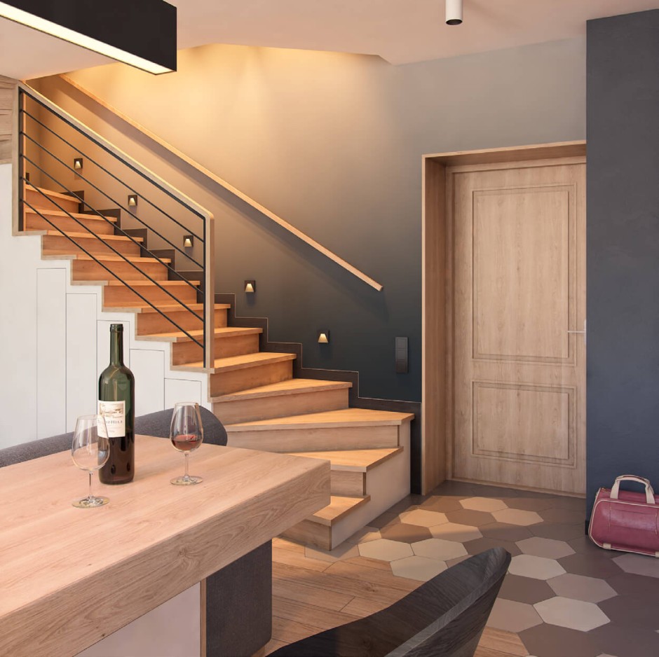
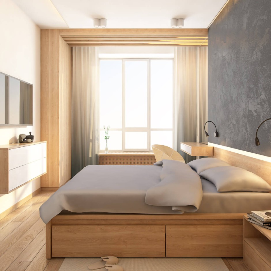
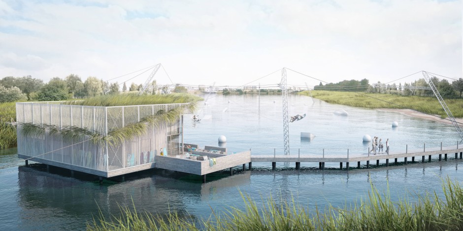
Archicad by Graphisoft has been around for more than 30 years. In that time, architects all over the world have come to know and appreciate it. Many other specialized software programs have appeared, but Archicad is also always on the move. My familiarity with the product began with its eighth version (i.e. in 2003), and since then I’ve urged people to design all components in this BIM environment. Starting with version 18, Archicad has incorporated the CineRender integrated visualization engine: a novelty that enables the entire project design cycle to be accomplished in one software program. Naturally, Archicad is not striving to achieve 100% photo-realistic rendering, but most users have virtually no idea about the capabilities of this engine. The Internet has many examples developed by architects from different countries. Fig.1 presents several images that I created. Please note that this level of quality would be more than sufficient for most tasks.
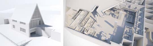
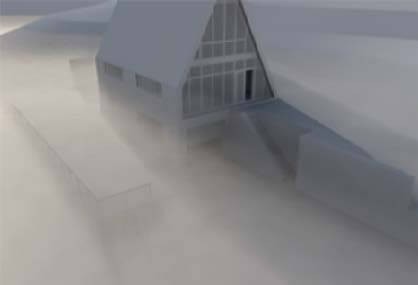
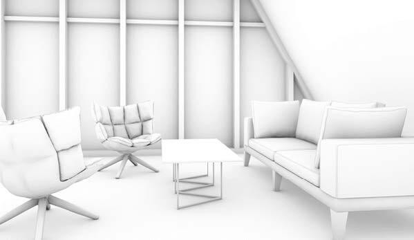
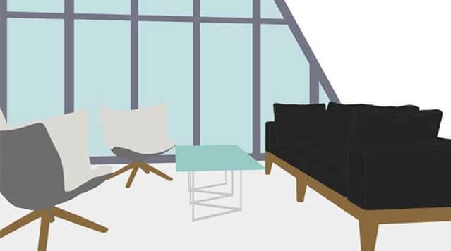
Let’s review the capabilities in more detail. If you are not limited to preconfigured scenes and can enable the display mode for detail settings, you can access the various effects and options the CineRender engine can offer. White Model is the most popular option. Once activated, it is possible to quickly obtain a picture that renders the general design volume and proportions (Fig.2).
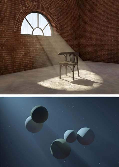
The Color Correction option allows you to change the image contrast and depth. The Shader Casting function can create a vignette, and Distance Fog can create fog. The Sharpen Filter feature in the Lens and Filters tab also deserves attention (Fig.3).
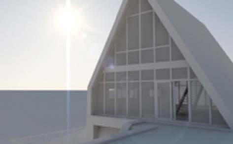
Lens Flare will activate flares included in the Light Sources parameters. Standard sun flares are included in the Environment– Sun section
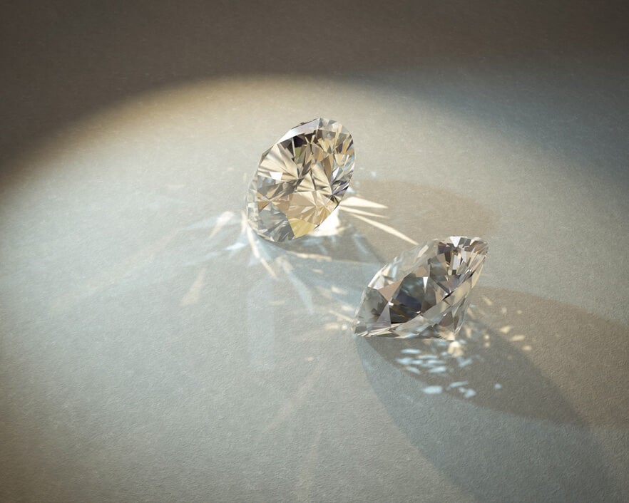
All these effects are certainly available in any graphics editor; however, if you need to quickly create images of acceptable quality, post-processing is not required once you have set the scene here. It is possible to include Caustics images in the Effects tab. If the light source and surfaces enabled in rendering also include caustics generation or reception, results like those shown in Fig.5 can be produced.
You might also want to experiment with the Depth of Field parameter. This setting allows certain objects to stay in focus, while the objects in the foreground and background will appear blurred (Fig. 6).
For basic rendering, the depth of field is included in the Effects section. The focus distance can be adjusted on both sides of the camera target. This function is described in sufficient detail in the reference manual.
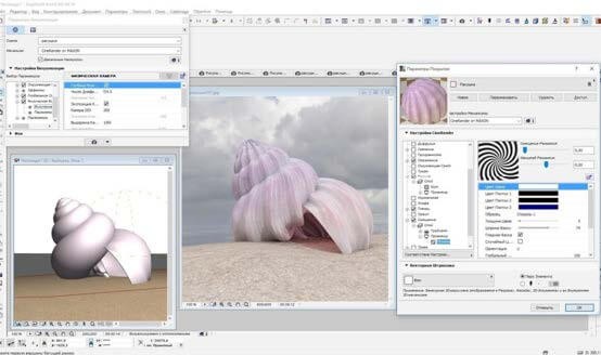
To enable physical rendering, the depth of field is included in the Physical Camera tab and depends on the F-stop value. The larger the value (f/2.0 > f/8.0), the greater the blur will be. At the same time, global illumination will be enhanced. Thus, it must be offset by a lower ISO value and/or exposure. In general, the physical rendering simulates real photo camera behavior. You may also designate a chromatic aberration and set the white balance here. The camera aperture shape influences the blurring shape: you can create both triangular and octagonal Bokeh flares. Using different weather settings produces interesting results with the Physical Sky enabled, which includes clouds, stars, rainbows, sunbeams, atmosphere and fog. The fog, for example, may incorporate shades and light within its depth (Fig. 7).
By default, practically all the scenes in the Main Parameters tab have Visible Light enabled (Fig. 8), but it won’t be considered until it is enabled in the light sources. You should note that this function is not available for all of the sources.
Let’s proceed with the surface parameter settings. Most situations require standard surfaces; additional surfaces can be retrieved from the library folder. I would like to note that CineRender in Archicad is mostly focused on procedural shaders; they can often be used for more quickly and attractively rendering bricks, parquet, tiles and stucco. As opposed to bitmap textures, they never repeat, which is very critical for large surfaces, especially in the event of exterior rendering (please, note the grey stucco in the top-left picture of Fig.1 and the brickwork in the bottom). Various noises, weathering and gradients create streaks and dirt on the surface.
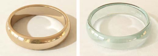
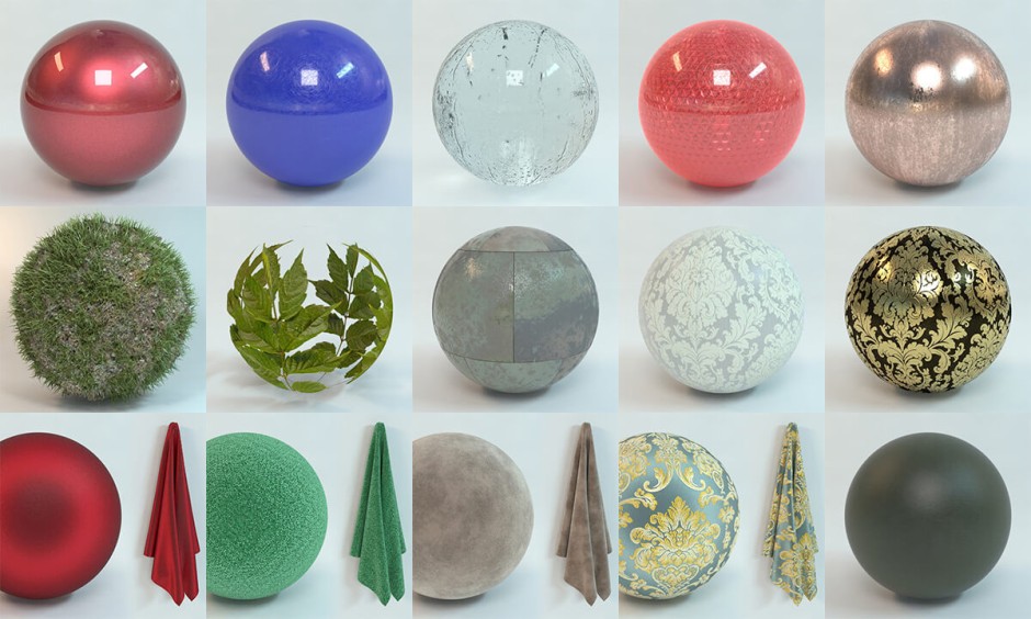
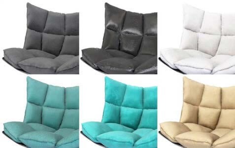
Using just a few surface parameter channels, you can generate completely different materials in terms of their visual perception. An example is shown in Fig. 9: The Color channel shows either noise or bitmap texture; almost all of the samples in Screen Above mode have Fresnel – depending on the view angle relative to the normal surface – overlaying the color. Due to the fibers, which diffuse light, nearly all of the fabrics look somewhat lighter at an acute angle. Certainly, all the material variations have the Bump channel enabled (leather texture is used for leather, fabric texture – for coarse fabric, a very small noise – for chamois), and various levels of Reflectance with Fresnel are included for leather.
Archicad 20 has a new Reflectance channel. Now you can create two different reflection layers, regulate the blur strength by mapping (procedural, bitmap or complex combination), and add the bump mapping to reflection layers, which does not affect other features. And in Archicad 21 you can use up to 10 reflection layers. So now, we have the opportunity to create surfaces with complex reflections. For example:
- Plastic, smudged with fingers, where one reflection layer has the minimum blur, but with fingerprints in the map mask; the second layer is heavily blurred with a finger mask, but inverted, a drop of the same bump mapping.
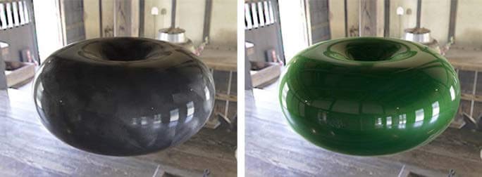
- Car paint, where the first reflection layer is green with small bump mapping and strong blurring, and the second layer with a sharp reflection simulates a lacquer application (Fig. 10).
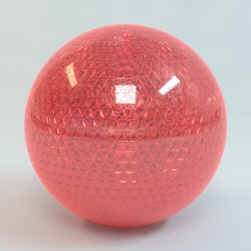
- Complicate transparent plastic with fals relief at inner side. Here is one layer with glossy reflect and small scratches, second reflect layer have bump with Procedural Shader “Tiles” (Fig. 11).
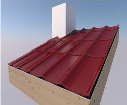
The Displacement channel deserves special attention. It produces an actual geometric deformation if rendered using black–and-white or red-and-green height maps. For example, in the Brightness mode, the black map areas remain in place and the white areas are raised to the maximum height. At a close view, shears can be seen, but for distant views, this method allows you to skip the modelling of millions of polygons (Fig. 12).
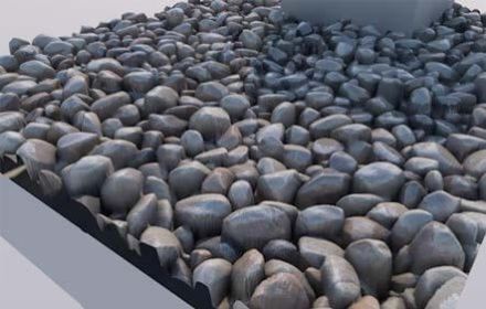
Special internet resources post plenty of specially developed seamless textures with displacement maps, which can also be used in Archicad. Example – Fig. 13: pebbles from free samples representing such textures.
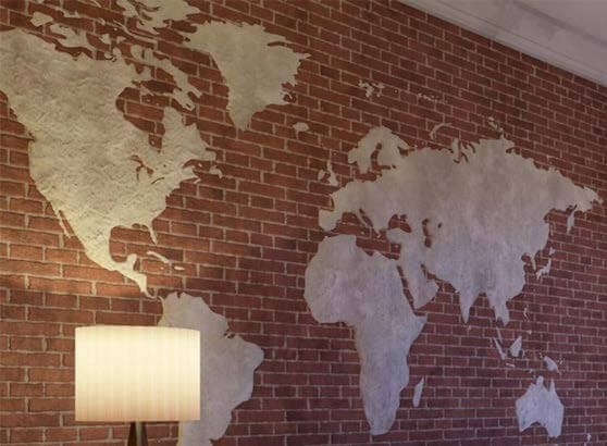
In the next example (Fig. 14) the black-and-white world map has a lick of paint at the edges to ensure a smoother thickness increment. In addition, bump mapping was used to render a little roughness.
“When activating the displacement with a minimum height that can barely be seen but allows the Smooth Geometry checkbox to be enabled, I achieved a result that was beyond my expectations! ”
Svetlana Kravchenko Architect
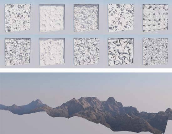
Various noises in the displacement channel produce interesting effects. The Luka noise produced the mountains shown in Fig. 15. The Atmosphere, included in the Environment parameters highlights the changes in the surface relief.
The rendering in Fig. 16 shows fabric folds in the background, which were created by displacement using the plain soft noise in portrait mode. In fact, this fabric is a flat rectangular morph (like the mountains in the previous Figure).
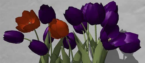
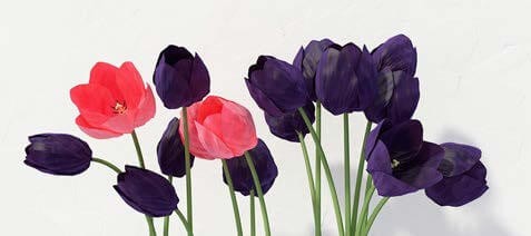
The displacement channel can be used to smooth objects with hard edges. As for the tulips (Fig.17-18), I purposely made them low-poly in GDL to plant an entire meadow with them. When activating the displacement with a minimum height that can barely be seen but allows the Smooth Geometry checkbox to be enabled, I achieved a result that was beyond my expectations! If displacement is used in combination with grass (with noise in the distribution density), you can obtain a realistic ground surface.
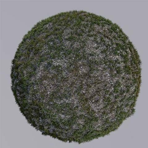
Even if the grass is represented by a dense carpet, it is better to add displacement, since CineRender cannot yet use maps to change the grass blade height (Fig. 19).
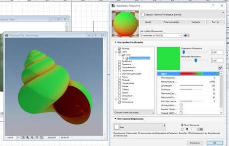
I would like to offer one more interesting example of surface experiments (Fig. 20) – in addition to complex displacement and bump mapping, the Ambient Occlusion Shader Effects was used in the Color channel (Fig. 21 demonstrates the functional principle of the Shader Effects).
The corner areas (“see less of the sky”) will pick up color that differs from the rest of the surface. Looking at the central shell more closely, you may notice that the colr is pale in the recessions and more intense and darker in the heights. The ambient occlusion is considered for the real geometry and the displacement-generated geometry as well.
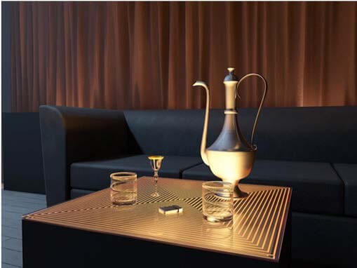
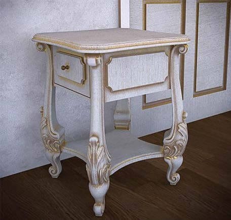
Thus, you can use occlusion to create patina in the recesses of the worn furniture, use it in the Color channel for darkening and the Reflectance channel to create a gilt effect (Fig. 22).
Next, you can check out one more occlusion option in the Glow channel. In all real photos of the lamp (Fig. 23), you can see that the intensity of the glow is highest in the areas within the depth, close to the lamp, while the glow value at the outer edges is lower. I could achieve this effect using the Shader Effects. The lamp looks great with both night and day rendering (Fig. 24).
Many material types (e.g. paraffin wax, porcelain, paper, and various fabrics for awnings) require using the Subsurface Scattering, ChanLum or Backlight Shader Effects in the Glow channel – as the case may be. Don’t forget to enable glowing surfaces in the rendering parameters!
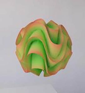
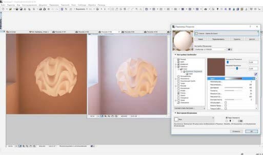
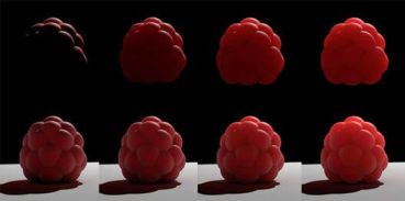
Fig. 25 illustrates the Subsurface Scattering function: starting from the left-hand side — its effect is zero and gradually increases moving to the right.
Fig. 26 shows examples of rendered surfaces with the effect disabled (on the left) and enabled (on the right). The Grass channel is the last one on the surface list, but you can use it to create not only grass, but for various furs (like those on the ant in Fig.26), and carpets (Fig. 27). Note that in case of nonphysical rendering, the grass blades won’t cast a shadow.
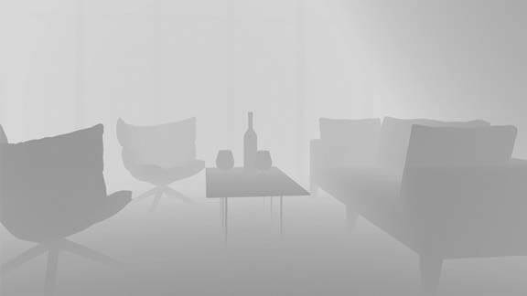
Now, a word about post-processing. For example, if the rendering is in V-Ray, you can save several images in addition to the primary image; they are called Render Elements. In Archicad, we can also create several and use them for further processing in the graphics editor. For example, we can render the depth map (Fig. 28).
In my YouTube account, I described how it can be done and used: Archicad 20 allows you to create a separate map with an ambient occlusion. For this purpose, all the surfaces in the project design will be replaced with one, specially-created surface where you should disable GI reception and generation, plus all the channels besides the glow channel, and place the occlusion in a way to highlight the corners. Disable everything (global illumination and illumination sources) in the visualization parameters, leaving only glowing surfaces and enable the Invert checkbox in Color Correction. When overlaying this map above the source image in multiplying mode, it is possible to adjust the corner shading using a mask in separate places (Fig. 29).
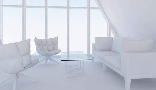
Using the white model and enabling definite light sources, we can render illumination maps for various sources and then illuminate required areas in the final render version (Fig. 30). Having saved the 3D document without shadows, you can generate a map of various surfaces (Fig. 31).
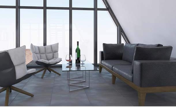
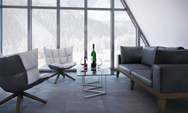
Fig. 32 shows the post-processing when using these maps
Of course, CineRender in Archicad will not produce the same results as specialized rendering software. There are still many limitations and open issues: it is not possible to regulate grass blade growth direction and height; there is no ability to copy layers in the surface settings; it takes a long time to count large quantities of polygons and blurs, etc. However, in my opinion, all the shortcomings are offset by the opportunity to do everything in one software program. Visualization allows the architect to deliver the project design image to the customer, which is not always possible to do using only layouts and façades. Direct rendering in Archicad will ensure the full compliance of the rendered image to the project drawings.
Svetlana Kravchenko
Svetlana Kravchenko has many other youtube video tutorials on the subject: here.
About Graphisoft
Graphisoft® ignited the BIM revolution in 1984 with Archicad®, the industry first BIM software for architects. Graphisoft continues to lead the industry with innovative solutions such as its revolutionary BIMcloud®, the world’s first real-time BIM collaboration environment; and BIMx®, the world’s leading mobile app for lightweight access to BIM for non-professionals. Graphisoft is part of the Nemetschek Group.